

Phone:+86 13333092057 Email: iasos@iasos.eu
Phone:
+30 6999398373 Email: coyote@iasos.eu
|
|
|
|
|
Phone:+86 13333092057 Email: iasos@iasos.eu |
Phone:
+30 6999398373 Email: coyote@iasos.eu |
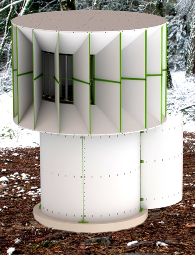
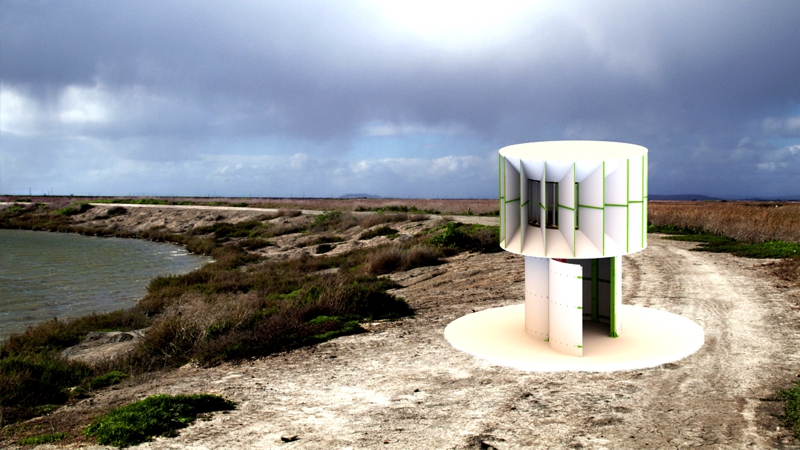
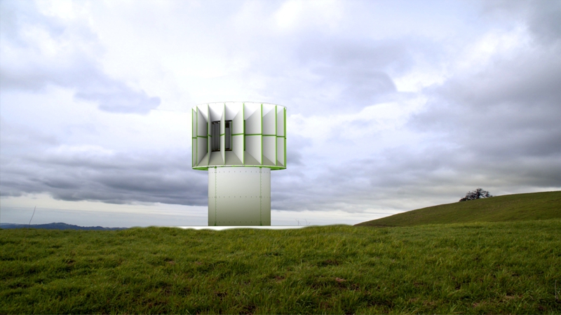
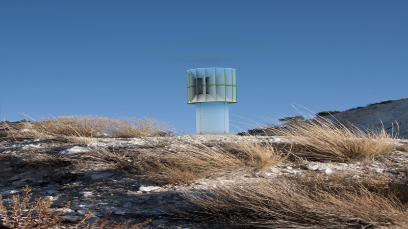
| Vertical
axis wind turbine:
"Iasos I". |
Nominal
power: 1 KVA |
| Download |
 |
||
|
Assembly and
installation instructions |
|
In
the box with the wind turbine parts, there is a CD with pictures to help
you with the assembly process. Components are divided into the following
categories: - "Components". - "Parts A". - "Parts B". - "LSU". - "RParts". Our factory produces and processes the components. Then we welds, paints and generally processes the components completely, thus producing "Parts A". After assembling "Parts A", at the final installation point, "Parts B" results. By assembling the "Parts B", results the "LSU" (Logical Sub Sectors) and of course the wind turbine as a whole. "RParts" are standalone equipment, which is installed on the wind turbine, for example the generator, "charger controller", etc. Each part has a code number. The image files on the CD are named after the code number of each part. First visit the "Parts A" catalog so you know the codes of the "Parts A" parts you will be using. If you consider it necessary, print the photos. You should know that the construction of all the components of the wind turbine has been done with CNC technology. All components ie, have been manufactured using computers and not by human hands. So, for example, a hole will never be in the wrong place. If during assembly you get the impression that a part does not fit in the intended position, then look for the solution in a previous stage of assembly and not in an error in the manufacture of the part. Never modify the holes in the fittings. When assembling, never use a metal hammer. Assembling the wind turbine is done following logical steps. Assemble the individual parts close to the concrete base of the wind turbine. With this way you will avoid the problem of having to transport larger and heavier parts to the final location. Follow step by step the photos on the CD, which you received together with the wind turbine. The name in the file of each photo tells you which part to use. The parts list and their corresponding photos are also on the CD. If you are struggling with the code numbers for screws and nuts, consider the following: - The diameter of each screw is denoted by the letter "M". Therefore, M6 means that the screw has a diameter of 6 mm. - The length, for all the screws used in the wind turbine, is a multiple of 5. The thickness of each plastic or metal part, which you should connect, is 5 mm or 10 mm. Therefore by adding the thickness of the components you will connect you can estimate the length of the corresponding screw, without constantly referring to the corresponding codes. |
|
|
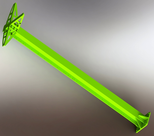
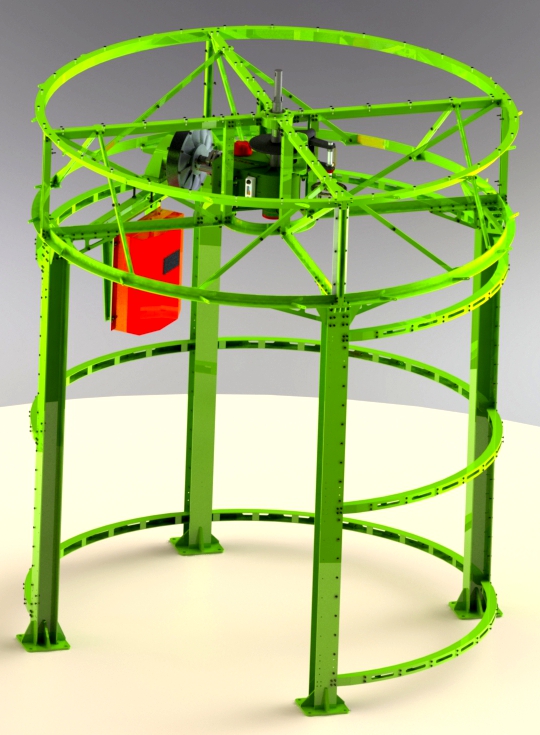
The individual
sections, of the wind turbine are:
1. |
|
 |
 |
|
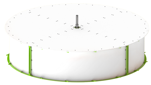
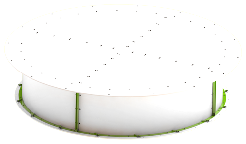
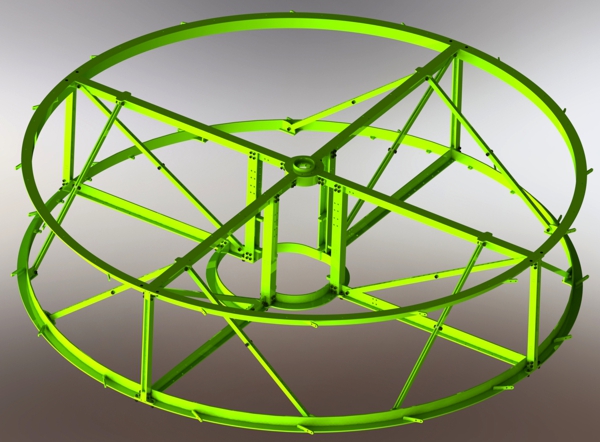
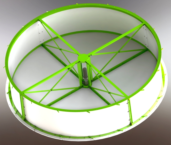
2. Lower Turbine Mount: Diameter: 2.12 m Height: 0.52 m Weight: 145 Kg On this particular base, the gear box, the generator and the manual brake are installed. During assembly, the upper plastic surface must be sealed so that the equipment underneath is protected from rainwater. |
|
 |
 |
|
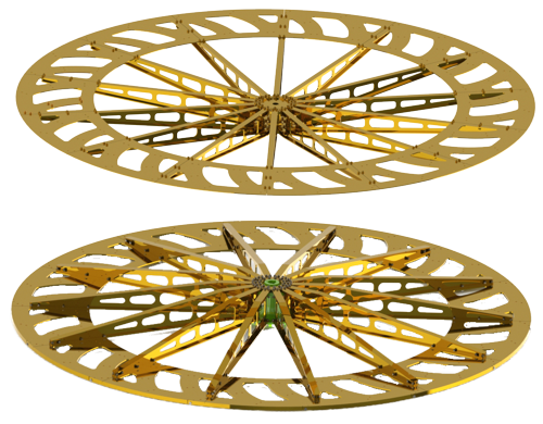
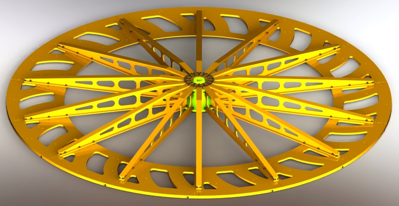
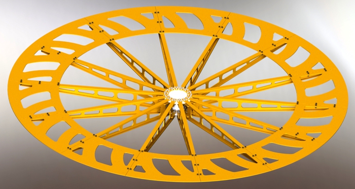
3. Turbine: Diameter: 2.08 m Height: 0.91 m Weight: 123 Kg The two turbine pulleys are made of 6061 T6 aluminum. They have been anodized. Each pulley has 14 spokes. The turbine has 28 blades, which are made of PVC using an extruder. |
|
 |
 |
|
4. Upper turbine mount: Diameter: 2.12 m Height: 0.52 m Weight: 105 Kg On the upper base of the turbine is installed the upper axis of rotation of the turbine. |
|
 |
 |
| Follow
the next steps to assemble the "Iasos" wind turbine. |
|
| Step
1. Start by assembling the "9901" part. It is the lower base of the turbine. When you finish assembling it, the "9901" part will weigh 107 Kg. Try to assemble all parts close to the final installation point to avoid carrying heavy parts. |
 |
| Step
2. |
 |
Step
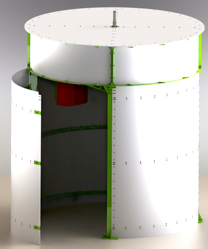
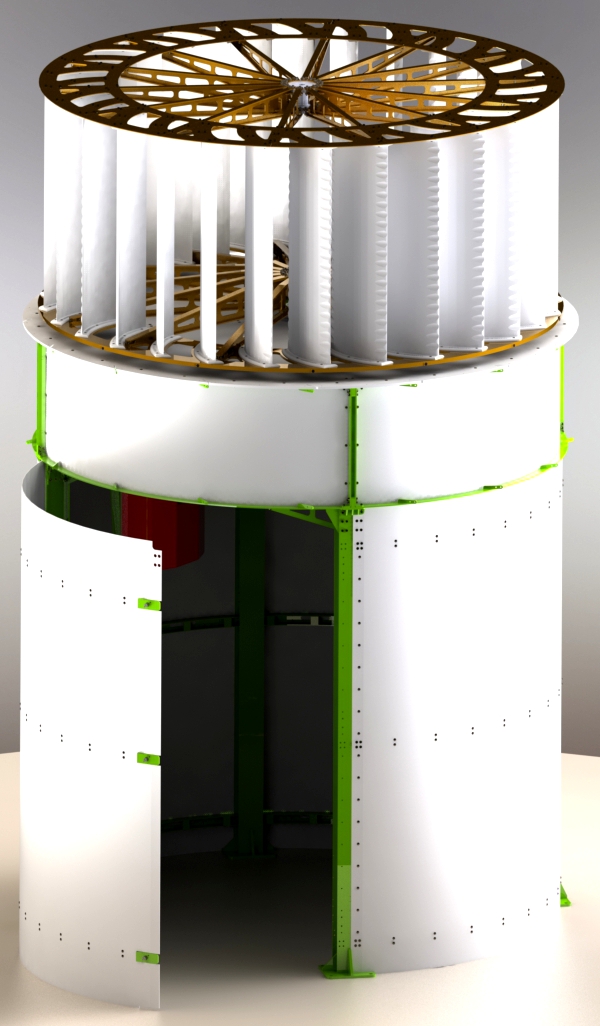
3. Then assemble the "9904" part. It's the door to the room, under the turbine. When finished, the door will weigh 37 Kg. It is noted that the door is of a light type. And the door, like all the side plastic coverings are there for aerodynamic reasons. They offer no protection against looting or rainwater. If you wish to protect this room effectively, you will have to build a wall on the outside yourself at a later time. Because we do not know the location and installation conditions of each of our wind turbines, the door has dimensions that exactly cover the empty passage inside the room (i.e., it has larger than "normal" dimensions). This can cause the outer plastic covering of the door to "drag" on the floor. If this is the case, feel free to trim the plastic door trim using a file. |
 |
Step
4. Then assemble the "9906" part. It is the lower pulley of the turbine. When finished, it will weigh 48 Kg. The individual parts of the pulley are made of aluminum 6063 T6, except for the central part, which is made of Cr42Mo4. At all stages of assembly, care must be taken to ensure that no weight is placed on the pulley, nor that people step on it. The pulley can accept a circumferential load of 2,500 N, but this does not mean that its stress is allowed. |
 |
Step
5. Then assemble the "9907" part. It is the upper pulley of the turbine. When finished, it will weigh 29 Kg. The individual pulley components are made of 6063 T6 aluminum. At all stages of assembly, care must be taken to ensure that no weight is placed on the pulley, nor that people step on it. Pulley strain is not permitted. If you are not experienced in assembly, it is better not to assemble this part completely at this stage of assembly. Assemble only the "501" center and "3010" spokes, not the "4010" peripherals parts. In this case you will finish assembling the part at a later stage. |
 |
| Step
6. |
 |
Step
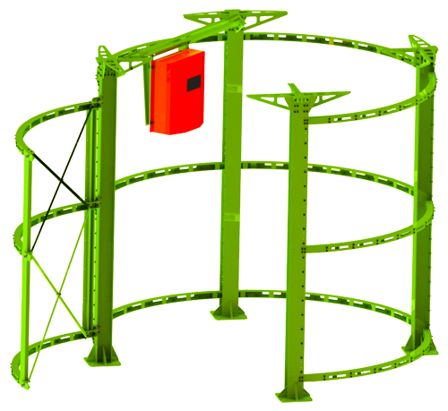
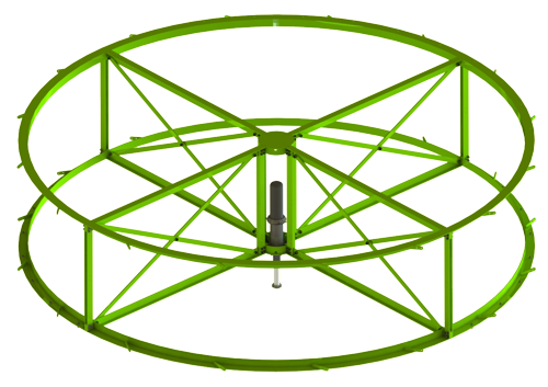
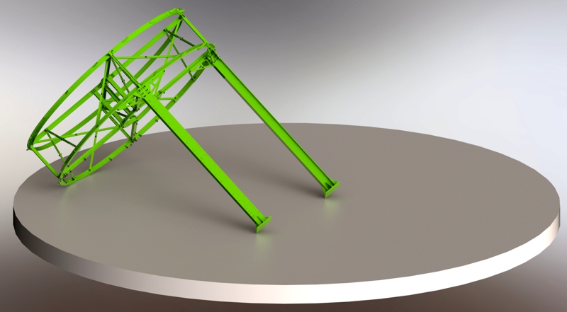
7. Next, assemble the "9903" part. Connect only two of the pillars to part "9901", part "9902", as in the photo. This way you will manage the weight better. |
 |
Step
8. Next, lift up part "9903" to assemble the other two pillars (parts "9902"). It will take two strong men. |
 |
Step
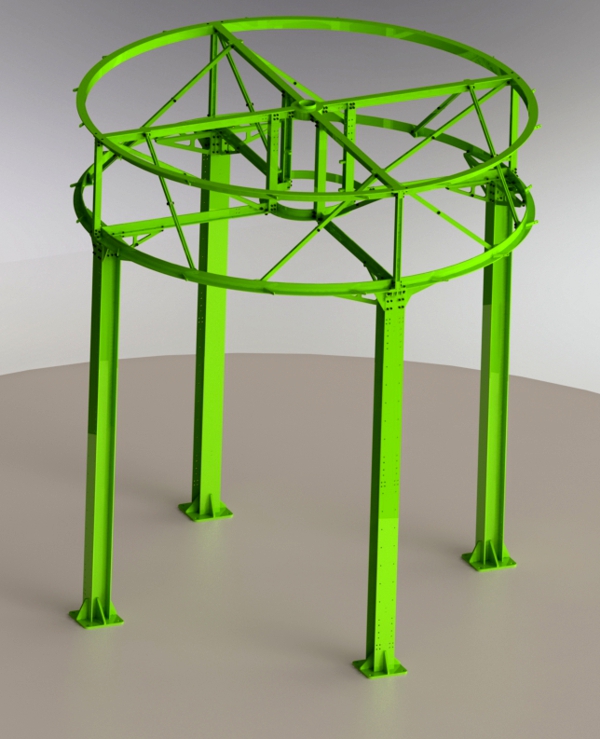
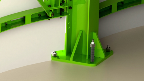
8.1. At this stage you should carefully connect the pillars to the concrete floor. |
 |
Step
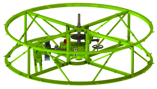
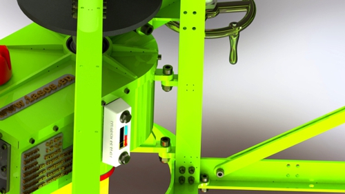
9. Next, assemble the "9905" part. At this stage the equipment should be placed inside the lower base of the turbine. First place the "gear box", then the generator base, then the "generator", then the "manual safety brake" and finally the "charger controller". If the weather is rainy, be careful not to get the related equipment wet. Equipment will no longer be at risk from rainwater when the top plastic covering is installed. |
 |
Step
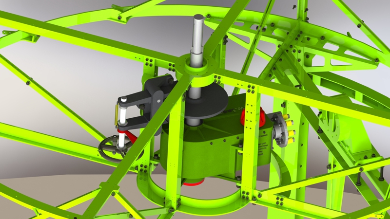
9.1. The gear box, part "G10065", should be lifted and placed on the corresponding stand, not suspended from it. There are a total of eight connection points of the gearbox to the turbine base. The "G10065" part weighs 53 Kg. Therefore two men will be needed to place it in the correct position. Make sure the lubricating oil level is at the correct level. |
 |
Step
9.2. The manual safety brake must be adjusted so that its jaws are equally distant from the two surfaces of the respective disc. Every time you work on the wind turbine, this brake must be active, i.e. "tight". |
 |
Step
9.3. When installing the generator, part "H8010", care must be taken to align the generator shaft with the gear box shaft. The two flanges through which the movement is transmitted from the gear box to the generator, should be parallel and 7.5 mm apart. The base of the generator can be adjusted in any direction. The generator weighs 24 Kg. The electrical connection of the generator is a "Y" connection. Connect the three wires of the generator to the "charger controller", part "H8520" and activate the electric brake of the "charger controller". The electric brake short-circuits the generator and prevents it from rotating. The shorted generator does not allow the gear box to rotate and this in turn stops the turbine. You should never apply the electric brake when the turbine is spinning. |
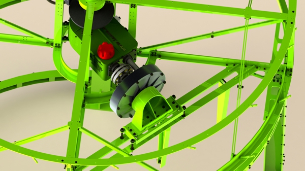 |
Step
10. When assembling, very carefully seal the two plastic covers of the turbine base, which have a code number: "6825 PSR 10". Use the silicone sealant found in the wind turbine box. Water must not pass downwards from this surface. It is the only surface of the wind turbine that prevents the passage of water. If at some point you find that the seal has failed, coat that particular surface with nitrile. When you have completed this assembly step, the "9905" will look like the next photo. In this phase, place the batteries and make all the electrical connections, according to the corresponding schematic diagram. The "charger controller" enables you to connect batteries with a total voltage of 48 DCV. The best type of batteries for the wind turbine are OPzV batteries. Each of these batteries has a voltage of 2 DCV. |
 |
Step
11a. Then assemble the "9908" part. It is the turbine of the wind turbine. Orient the spokes of the upper pulley so that, viewed from above, they are in between the spokes of the lower pulley. When you finish assembling the turbine it will weigh 125 Kg. To fit this part to the central shaft, which protrudes from the top of the gear box, you will need to raise it by 2.6m. If you cannot lift this weight, then you can gradually assemble this part, working on the gear box shaft. To lift, move part "9908", it should be grasped by the spokes of the lower pulley, part "9906". If you try to lift this part by holding it by the peripheral parts or by the top pulley, you may cause distortions, which can become a problem. |
 |
Step
11b. If you are not experienced in assembly, it is possible that at a later stage of assembly you will encounter difficulties with the part "9908". For this reason, it is better to assemble the part as in the next photo, ie, let the center part of the upper pulley just "sit" inside the turbine. Thus, when at a later stage of assembly the upper turbine shaft needs to be connected to the upper pulley, you will be able to do so more easily. |
 |
Step
12. Place the turbine "9908" on the part "9905", in such a way that the central shaft is correctly connected to the lower pulley of the turbine. If for any reason you want to get inside the turbine, temporarily disassemble two of the blades. Whenever someone enters the turbine, care must be taken not to distort the lower pulley spokes (rods) with their weight. |
 |
Step
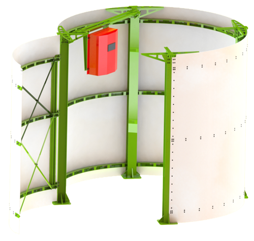
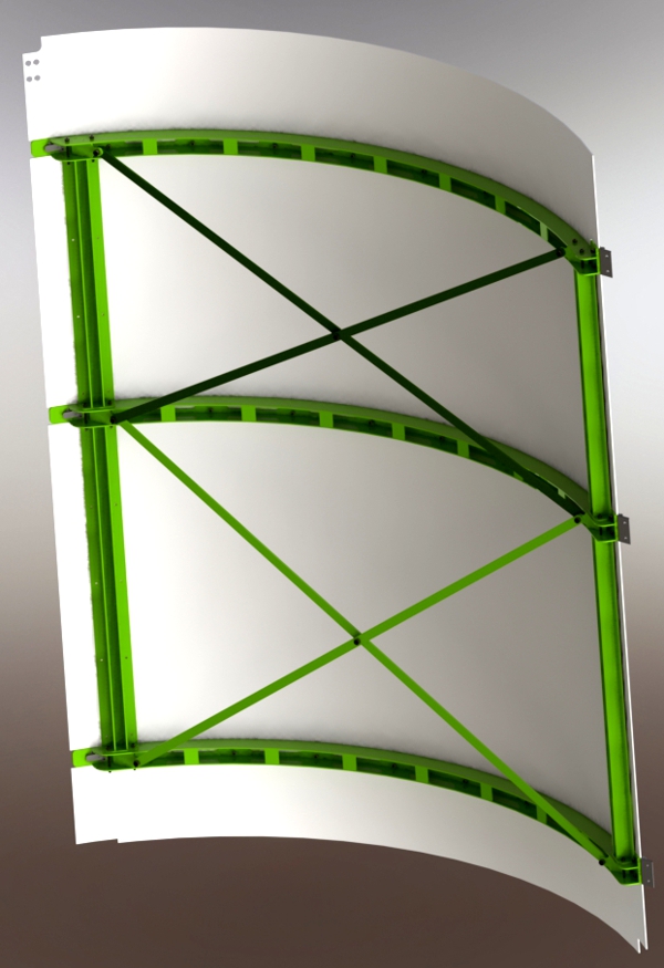
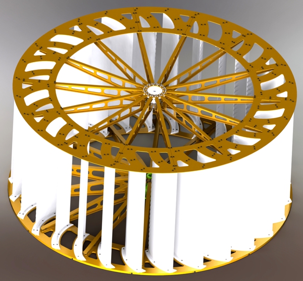
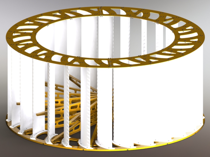
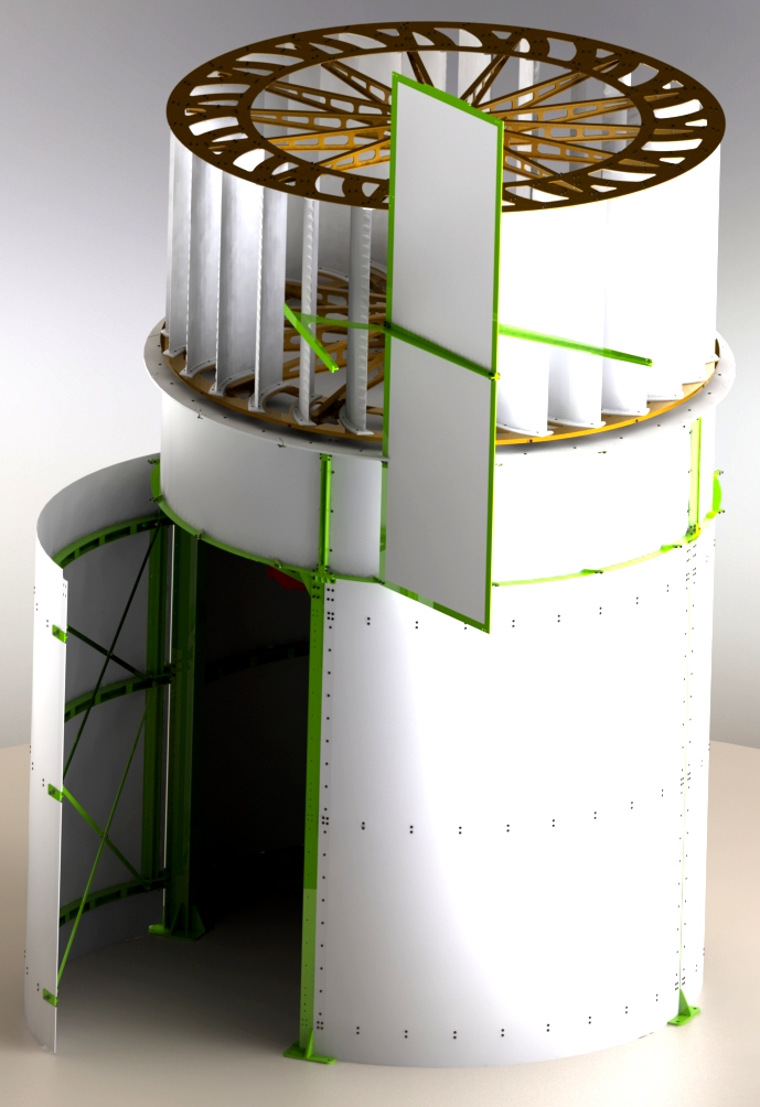
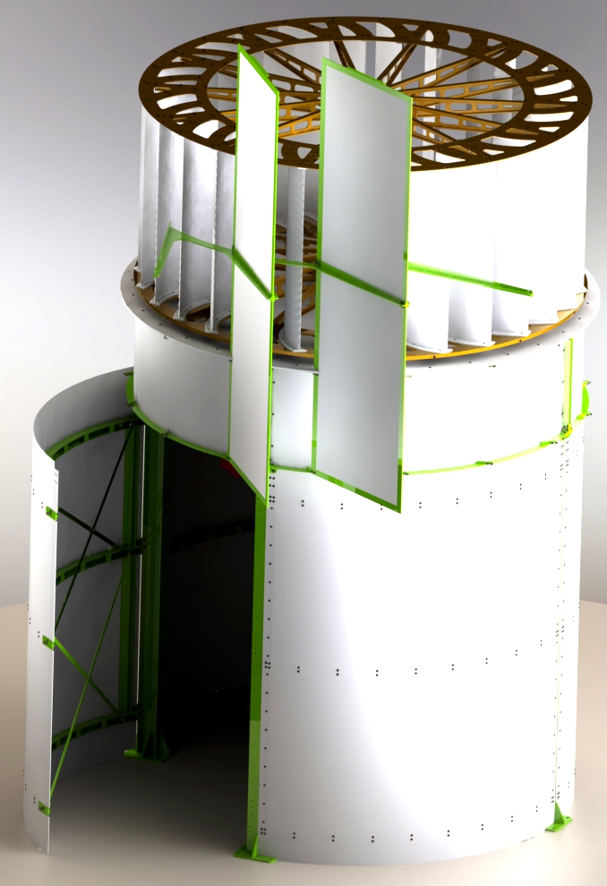
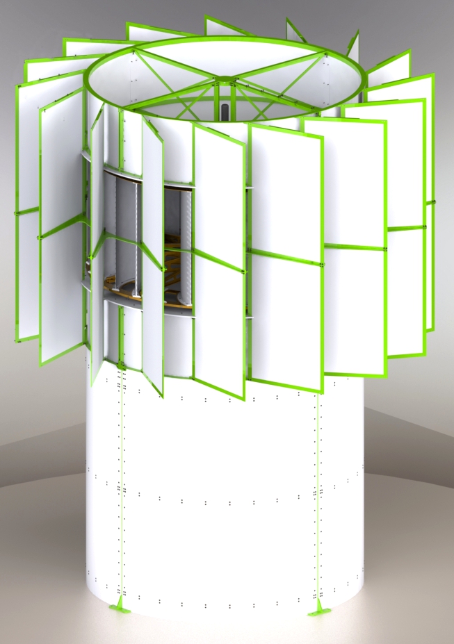
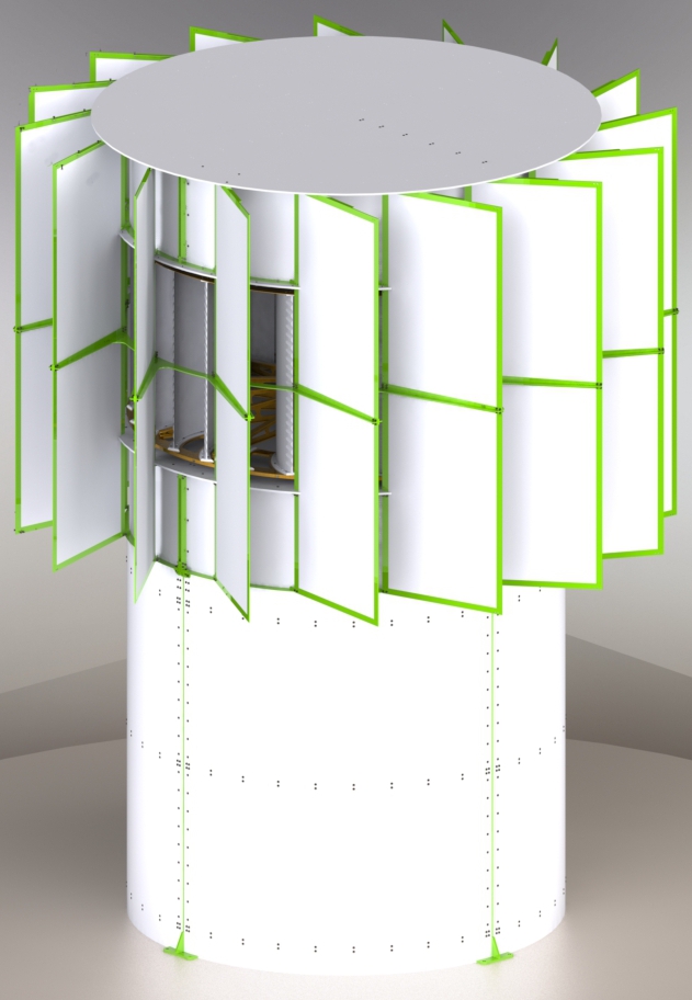
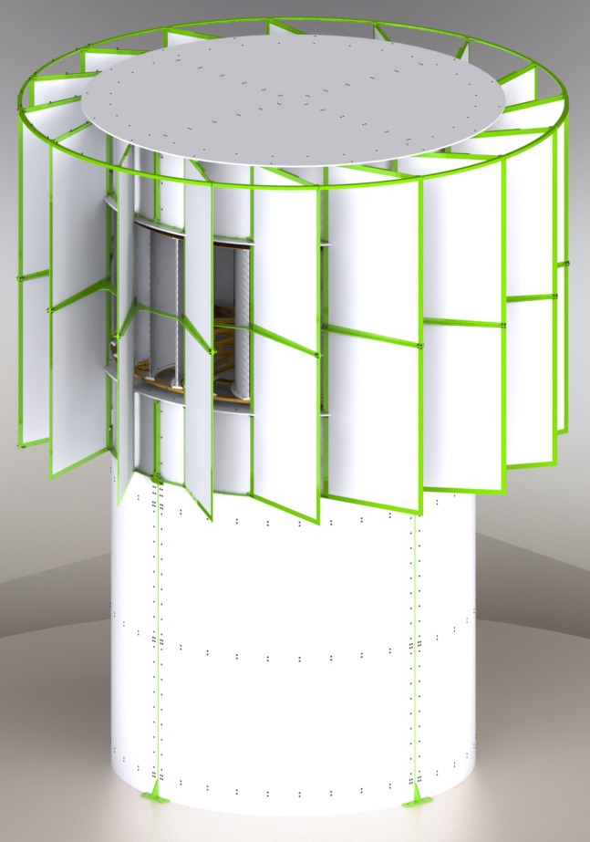
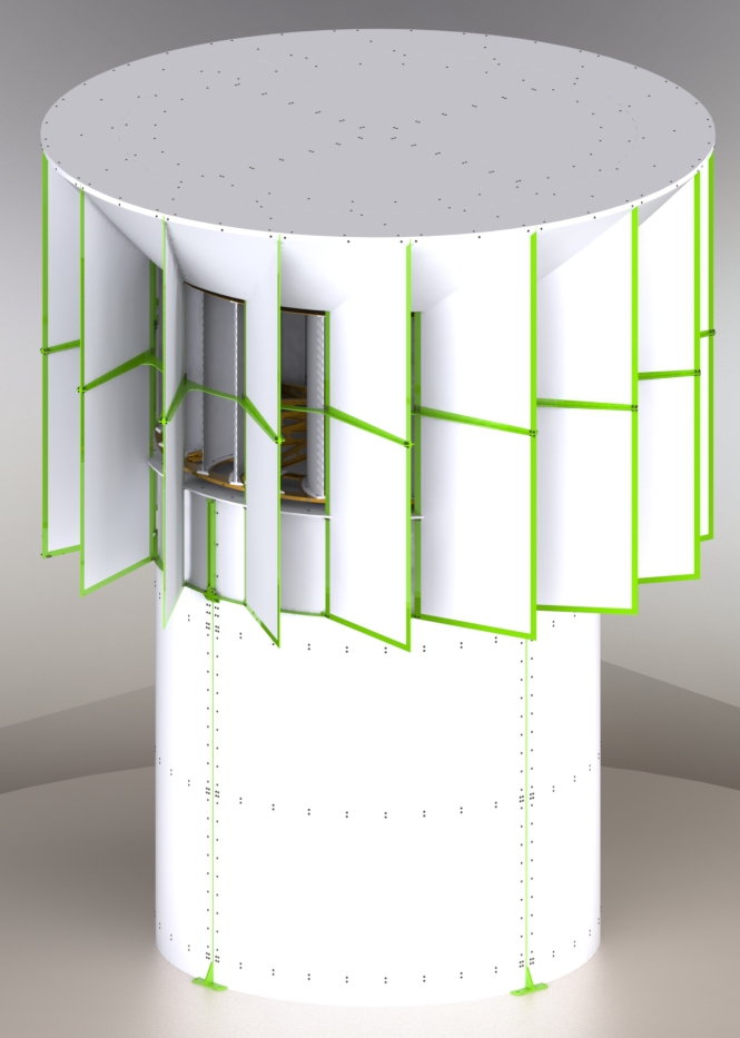
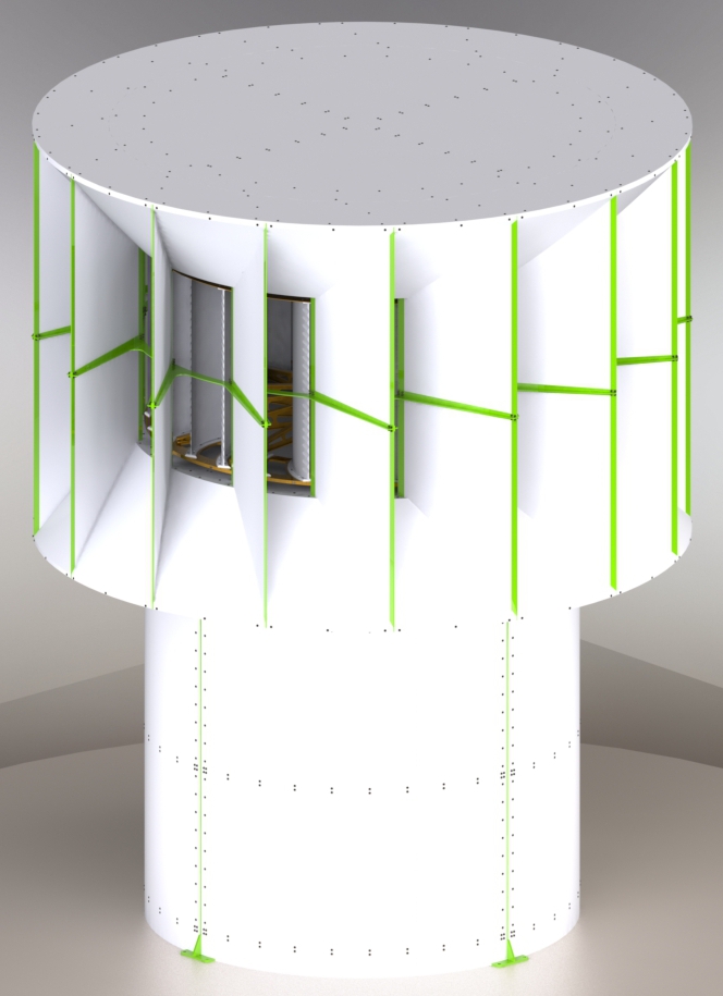
13. In this step you should assemble the vertical and horizontal diffusers. First assemble a single vertical diffuser with two horizontal diffusers and place them in the correct position. Even if you have already installed the screws that hold the diffuser in place, a person must hold it from the top so that it does not bend. This should continue until at least 8 of the 16 vertical diffusers are assembled. If the plastic surfaces of the vertical diffusers do not stabilize in the correct position, don't worry. A later assembly stage will solve this problem. |
 |
Step
13a. Continue assembling, one by one, in a circle, the diffusers. |
 |
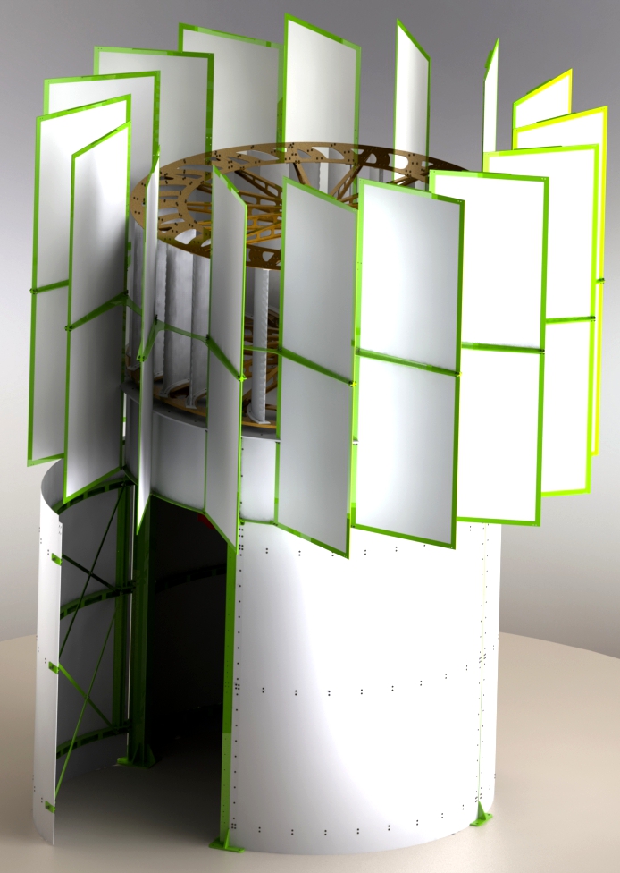
Step
13b. When you finish assembling the diffusers, the wind turbine will look like the next photo. |
 |
Step
14. When assembling the wind turbine, this assembly step is the most difficult. Not only because the upper turbine base, part "9910" has to be raised by 4.5 m and placed in the correct position, but mainly because the upper shaft of the wind turbine has to be connected to the upper pulley of the turbine. One way, which facilitates the process, already mentioned in a previous stage of assembly (11.b.), is not to complete the assembly of the turbine in advance. The upper pulley is not screwed into place and is simply resting on the inside of the turbine. Therefore, in the current assembly phase, the upper pulley can be lifted into position so that the upper shaft of the wind turbine can be connected to it, and then the upper pulley can be bolted to the turbine blades. Even in this case someone will probably have to get inside the turbine to tighten the upper shaft nut. It was already mentioned above that this can be done by temporarily removing two turbine blades. It is noted that all the nuts of the mechanism of the upper shaft of the wind turbine are counter-clockwise. |
 |
Step
14a. The next picture shows the upper turbine shaft, part "9927". |
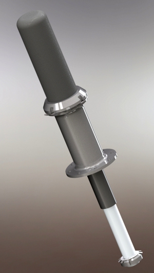 |
Step
14b. The next photo shows the upper axle already in place. |
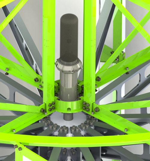 |
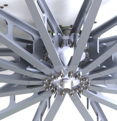
Step
14c. After the upper shaft of the wind turbine is connected to the turbine, it must be adjusted. The adjustment is made from the roof of the wind turbine and after removing the rubber cover of the adjustment mechanism. To adjust the upper axle, turn the adjusting nut to the left until the spokes of the upper pulley form a horizontal plane. In no case do we tighten the upper shaft too much to transfer a vertical load from the weight of the turbine to it. |
 |
| Step
15. |
 |
Step
16. Install the "9824" parts of the upper ring. |
 |
Step
17. Complete the assembly of the roof, putting the tapered overlays. |
 |
| Step
18. Just
release the manual safety brake and the electric brake on the "charger
controller". |
 |
 |
 |
 |